
What Is Rotor Flux Monitoring?
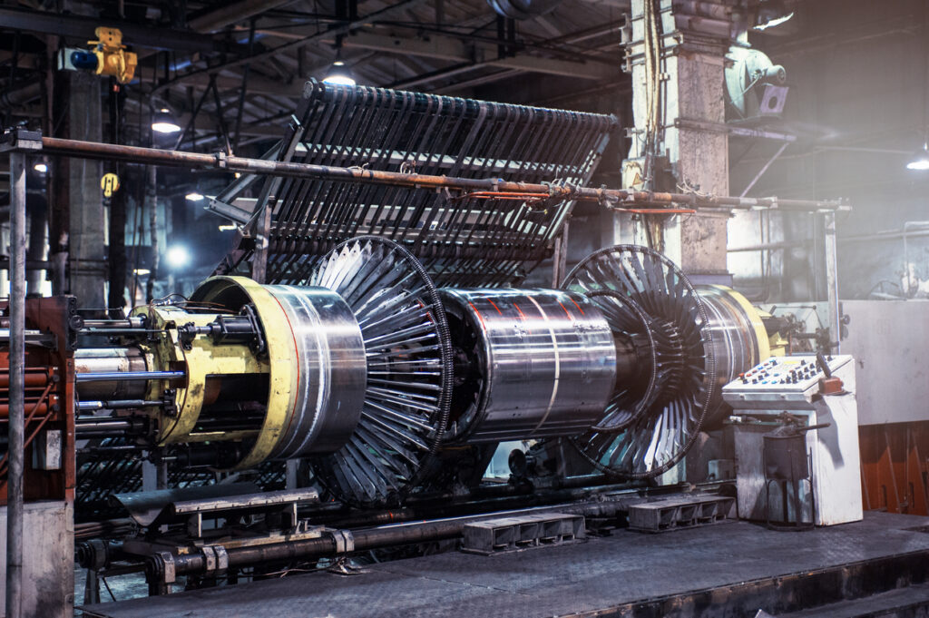
A generator rotor spends its life in a punishing environment. It spins at 3,600 RPM inside a hydrogen or air-cooled enclosure, carries thousands of amps of DC excitation current, and cycles through thermal and mechanical stress every time the unit starts, stops, or swings load. The insulation between the rotor field winding turns absorbs all of it. When that insulation finally gives way, the failure does not announce itself. It begins as a single shorted turn that slightly reduces the magnetic field of one pole and produces a small thermal imbalance in the rotor body.
That small imbalance is the beginning of a chain reaction. Rotor flux monitoring exists to catch it while it is still small, and to do so without taking the unit offline.
Table of Contents
- What Is Rotor Flux Monitoring?
- How Rotor Flux Monitoring Works
- Failure Modes Rotor Flux Monitoring Detects
- Continuous Monitoring Compared to Periodic Testing
- What to Look for in a Rotor Flux Monitoring System
- Where Rotor Flux Fits in a Generator Monitoring Program
- Getting Started
What Is Rotor Flux Monitoring?
Rotor flux monitoring is a predictive maintenance technique that measures the electromagnetic field produced by a generator rotor in order to assess the electrical balance, magnetic symmetry, and overall condition of the field winding. It is performed while the machine is running under real operating conditions, which is what separates it from the offline electrical tests traditionally used to evaluate rotor windings.
The physical principle is straightforward. Each pole of a healthy rotor produces a magnetic field of expected strength and shape. A flux probe mounted in the air gap sees that field pass by once per revolution and generates a voltage waveform that traces the field profile coil by coil. If every coil is intact, the waveform is symmetric and repeatable. If a turn shorts, that coil produces measurably less flux than its counterparts, and the asymmetry appears in the waveform.
The consequences of ignoring that asymmetry are what make the measurement worth taking. Variances in magnetic flux inside a generator indicate deterioration of winding insulation, whether the root cause is thermal wear, load cycling, contamination, or large variation on load. Imbalance within the rotor damages insulation further, which degrades output capacity and increases vibration. The added vibration damages more insulation. Left alone, the cycle ends in a forced outage.
Cutsforth's rotor flux monitoring system is built to interrupt that cycle by making the asymmetry visible early and trending it over time rather than sampling it once a year.
How Rotor Flux Monitoring Works
A rotor flux monitoring system has three parts: the probe in the air gap, the acquisition hardware that digitizes its output, and the software that turns the waveform into a diagnosis.
The probe itself is typically already installed. Cutsforth does not manufacture or sell flux probes, and the monitoring system is deliberately agnostic to probes already in the field. Any analog probe supplying plus or minus 10 volt inputs will work, which means most units with an existing probe can be brought online without touching the air gap. Installation is non-invasive and does not require an outage.
The acquisition side is where fidelity matters. The Cutsforth system samples the rotor flux signal at over 50 kHz, which preserves the fine structure of each coil transition rather than smoothing it away. At 3,600 RPM the entire rotor passes the probe in about 17 milliseconds, so the difference between adequate and high-speed sampling is the difference between seeing a coil-level anomaly and averaging it out of existence. Machines with more than two poles require a keyphasor input supplying one pulse per shaft rotation so that each waveform can be indexed back to a specific physical coil.
Analysis happens in InsightCM. As waveforms are processed in real time, the system identifies the peak voltage amplitude of each coil, plots the Flux Density Curve, and locates the Flux Density Zero Crossing, the point at which the integral of the flux waveform reaches zero volts. From there it calculates maximum flux deviation, the percent deviation associated with the zero crossing, and a per-coil table showing deviation and estimated number of shorted turns. Those values are trended over time, which is the part that actually drives decisions. A single reading tells you what the rotor looks like today. A trend tells you whether the condition is stable or progressing, and how fast.
Setup requires baseline waveforms captured across defined operating states, including just before the unit spins up on turning gear and during spin up just before it comes online. Alarms are only valid when the generator is online, so establishing the correct operating state logic up front is what keeps the system from producing false faults during startup and shutdown.
Failure Modes Rotor Flux Monitoring Detects
Rotor flux monitoring is a targeted measurement, not a general-purpose one. It is specifically effective against four conditions:
- Turn-to-turn shorts. Failure of the insulation between adjacent turns in the field winding. This is the primary target and the condition rotor flux monitoring detects earliest.
- Field winding open circuits. A break in winding continuity, which alters the flux contribution of the affected coil in a distinctly different way than a short.
- Uneven magnetic field distribution. Asymmetry across poles that produces unbalanced magnetic pull, a direct contributor to increased vibration.
- Insulation degradation and overheating. Progressive thermal damage that shows up as gradual drift in coil-level flux measurements before any hard short develops.
The value of catching a shorted turn early is not that one shorted turn is dangerous by itself. Many machines operate for years with a small number of shorted turns and no operational consequence. The value is knowing the count, knowing whether it is growing, and being able to schedule the rotor rewind or repair into a planned outage rather than discovering the problem when a vibration alarm trips the unit at an inconvenient moment.
Continuous Monitoring Compared to Periodic Testing
Most plants encounter flux testing as a periodic service. A third-party vendor arrives once a year, connects portable equipment, sweeps the unit through a load range, produces a report, and leaves. It works, but it has structural limitations. It is expensive on a recurring basis, it captures a very small snapshot of the machine's operating life, and the plant frequently does not own the underlying data.
Continuous monitoring inverts that arrangement. The system is a one-time purchase that collects data and builds waveforms across thousands of frequencies, allowing the plant to measure and archive over time and form a far more complete picture of generator health. The data belongs to the plant, with no recurring fee to access its own history.
Offline testing still has a role. Recurrent surge oscilloscope and pole drop tests performed during outages remain valuable for confirming and localizing a fault, and industry guidance on diagnostic field testing of large rotating machines, including IEEE Std 62.2, documents the range of applicable tests and their limitations. The practical point is that offline tests answer a different question. They tell you what the rotor looks like when it is cold and stopped. Rotor flux monitoring tells you what it does under load, at temperature, at speed, which is where centrifugally-induced and thermally-induced shorts actually appear.
| Approach | Data frequency | Outage required | Data ownership | Best suited for |
|---|---|---|---|---|
| Continuous rotor flux monitoring | Continuous, across all operating states | No, non-invasive installation | Plant owns and archives all data | Trending progression and driving outage planning |
| Annual third-party flux testing | One snapshot per year | No, but requires vendor mobilization | Typically retained by the vendor | Occasional verification with no installed capability |
| Offline electrical testing | Only during planned outages | Yes | Plant owns test records | Confirming and localizing a known fault |
What to Look for in a Rotor Flux Monitoring System
Several capabilities separate a system that produces usable diagnostics from one that produces a data archive nobody reads.
Sampling rate. Coil-level resolution requires high-speed acquisition. Sampling well above 50 kHz preserves the transitions that distinguish a shorted turn from measurement noise.
Probe compatibility. A system that requires proprietary probes forces an air gap intervention and an outage. Probe-agnostic acquisition that accepts standard analog inputs removes that barrier entirely.
Operating state awareness. Flux measurements are only meaningful in context. Excitation current and load both change the flux signature, so the system must know what state the machine is in before it evaluates a deviation. Without configurable operating states, alarms fire on normal startup behavior and the plant learns to ignore them.
Configurable alarms with full data capture. User-defined thresholds should be associable with multiple features, and a triggered alarm should capture the complete dataset rather than a summary value. An analyst reviewing an event three weeks later needs the waveform, not a number.
Access to expertise. Flux waveform interpretation is a specialized skill. Cutsforth provides access to subject matter experts to assist with reading and analyzing the data, which matters most in the first year of a program when the team is still building interpretive confidence.
Where Rotor Flux Fits in a Generator Monitoring Program
Rotor flux monitoring answers one question extremely well and says nothing about the rest of the machine. A shorted turn produces unbalanced magnetic pull that raises vibration, so correlating flux data against vibration confirms a diagnosis that either measurement alone would leave ambiguous. Thermal degradation of rotor insulation frequently coincides with cooling system issues that IR thermography would surface first. Excitation problems overlap with what electromagnetic interference monitoring detects.
This is why Cutsforth positions rotor flux inside a multiphysics approach. Generator monitoring spans generator field monitoring, brush condition monitoring, shaft ground monitoring, vibration analysis, electrical signature analysis, electromagnetic interference monitoring, IR thermography, and lubrication and oil analysis. Each technology has blind spots. Deployed together through a single platform, they cover for one another, and InsightCM correlates rotor flux against vibration, temperature, and electrical data in one view instead of three disconnected systems.
For plants building the financial case internally, the Reliability ROI Calculator helps translate avoided forced outage risk into the language leadership uses when evaluating capital requests.
Getting Started
The practical starting point is inventorying what you already have. Many generators were built with a flux probe already installed in the air gap that has never been continuously monitored, which means the sensing hardware cost is already sunk and the path to continuous coverage is shorter than most teams assume. From there, the questions are which units carry the highest consequence of a forced outage, what excitation and operating data is available to provide context, and whether a keyphasor signal exists on multi-pole machines.
Cutsforth brings more than 30 years of generator reliability experience to that assessment, along with engineering support from implementation through ongoing operation. Contact Cutsforth to talk with an expert about your units, your existing probe configuration, and what continuous rotor flux visibility would look like at your facility.
About the Author

John Pasquarette is a product and marketing leader with a long track record in industrial technology, engineering software, and IoT sensing. He has led product and marketing teams at companies including Cutsforth, National Instruments and Monolith, where his work has centered on helping engineers and manufacturers turn sensor data and analytics into better decisions. Based in Austin, Texas, he writes and speaks on condition monitoring, predictive maintenance, and the Industrial Internet of Things.